
How to adjust valves toyota avanzaWhat causes you want to set the valve toyota avanza, toyota engine avanzaku whether the sound rude? or lack of energy avanzaku toyota engine, toyota engine speed may be unstable avanzaku or so-called lame avanzaku toyota engines.If you have a complaint please follow these instructions how to adjust valves toyota avanzaku as follows:1.OFF THE CABLE FROM NEGATIVE BATTERY TERMINAL
# Loosen the hose clamp and the air filter off the bolt, then remove the air cleaner hose No. 1.
 2.Hose OFF AIR FILTERS NO 1
# Disconnect the VSV connector.
# Remove the 2 hoses.
# Remove the air temperature sensor.
# Unplug the vacuum sensor.
# Remove the vacuum hose.
# Remove the 3 bolts, then remove the air filter sub-assembly.
3.OFF AIR FILTER ASSEMBLY
# Remove the four connectors.# Remove the four bolts, then the ignition coil assembly.
 4.IGNITION COILS OFF ASSEMBLY
5.OFF VENTILATION HOSE
6.OFF VENTILATION HOSE NO 2
7.OFF THROTTLE BODY BRACKET NO 2
# Remove the 2 screws, then remove the throttle body bracket 2.
8.DETACH CABLE MACHINE
9.DETACH PIPE RADIATOR SUB-ASSEMBLY
Remove the 2 screws, then remove the radiator pipe sub-assembly.
 10.OFF CYLINDER HEAD COVER SUB-ASSEMBLY
# Remove the 11 bolts and 2 nuts in the order indicated in the figure, then the cylinder head.
11.CHECK SLIT VALVE
CAUTION:Check the valve gap in cold conditions.
# Set the 1 cylinder to TDC / compression.
 * Rotate the crankshaft clockwise, to align the timing mark of crankshaft pulley with the pointer on the timing chain cover.
 # Check that the adjustment mark on the camshaft timing sprocket is facing up. If not, turn the crankshaft 1 round until the signs are facing upwards.
# Check the valve gap shown in the picture.
* Use a feeler gauge, measure the gap between the valve lifter and camshaft.
Slit valve (Cold):Intake 0.145 to 0.235 mm (0.0057 to 0.0093-in.)Exhaust 0.275 to 0.365 mm (0.0108 to 0.0144-in.)
 INSTRUCTIONS:If the gap is not in accordance with specification, record the measurement results are outside specification.
# Rotate the crankshaft clockwise one full turn and set cylinder No.. 4 to TDC / compression.
# Check the valve gap shown in the picture.
* Use a feeler gauge, measure the gap between the valve lifter and camshaft.
Slit valve (Cold):Intake 0.145 to 0.235 mm (0.0057 to 0.0093-in.)Exhaust 0.275 to 0.365 mm (0.0108 to 0.0144-in.)
 INSTRUCTIONS:If the gap is not in accordance with specification, record the measurement results are outside specification.
12.SET THE SLIT VALVE
CAUTION:To prevent the valve does not collide with the piston when removing the camshaft, rotate the crankshaft in the direction of engine rotation approximately 90 ° from TDC / compression cylinder No.. 1.
 # Remove the 2 screws, then remove the chain vibration damper 2.
 # Remove the two bolts and timing chain cover stars. 2.
 # Rotate the crankshaft pulley clockwise and 2 screw loose.
 # Rotate the crankshaft clockwise, to align the timing mark of crankshaft pulley with the pointer on the timing chain cover.
# Check that the adjustment mark on the camshaft timing sprocket is facing up. If not, turn the crankshaft 1 round until the signs are facing upwards. (No. Cylinders. 1 at the position of TDC / compression).
# Give the paint mark on the timing chain is a straight plate with marks on the camshaft timing mark on camshaft sprocket and timing gear.
# Using a hexagonal lobes on the camshaft, loosen the screws that secure the camshaft timing sprocket.
CAUTION:The bolts can only be relaxed. Do not remove the bolts and sprockets.
 INSTRUCTIONS:Loosen the bolt forward. If the bolt relaxed after removing the chain, the chain will be disrupted by the sprocket.
 # Use a 10 mm hexagon key, remove the screw hole plugs chain service cap.
# Insert the screwdriver into the hole closed service chain, then move the stopper plate on the tensioner downward and hold it so as not to lock.
 INSTRUCTIONS:This operation unlock the plunger on the tensioner.
# If the stopper does not release the lock plate easily, turn to the right and left to use hexagonal lobe on the camshaft.
 # Using a hexagonal lobes on the camshaft, rotate the camshaft slightly to the right so that the plunger on the tensioner driven by chains.
# Remove the screwdriver from the hole closed chain services. Align the holes in the stopper plate and tensioner, then enter the lock hexagon diameter 2.5 mm (0.098-in.).
CAUTION:
*Hold the camshaft using the hexagonal lobe on the camshaft.
# Hold the diameter of 2.5 mm hexagon key (0098-in.) With adhesive tape so as not to be attracted to the outside.
 INSTRUCTIONS:This operation is to hold the plunger on the tensioner in place.
 # Remove the bolts fringe, then release chamshaft timing sprocket.
 #Remove the bolts and loose chamshaft timing sprocket assembly.
 #Remove the camshaft bearing cap No.. 1 and no. 2 in the sequence shown in FIG.
 #Hold the timing chain by hand, then remove the camshaft. After removing the camshaft, hold down the chain by inserting a metal rod to prevent dropped chains.
# Use a micrometer, measure the thickness of the valve lifter that has been released.Calculate thick slit valve lifters so the valves are in the specification.
A. Choosing valve lifter.
B. Bold valve lifter is released.
 C. Measurement slit valve.
Value specification (Cold):
Intake A = B + (C - 0.18 mm (0.0071-in.)).
Exhaust A = B + (C -0.31 mm (0.3099 mm.)).
# Select the new lifters with a thickness as close as possible to the value has been calculated.
INSTRUCTIONS:Lifter is available in 29 sizes with the addition of 0.020 mm (0.0008-in.), From 5.12 mm (0.2016-in.) Up to 5.68 mm (0.2236-in.).
Gap intake valves (Cold):Intake 0.15 to 0.23 mm (0.0059 to 0.2311 mm.)
EXAMPLE:Posted lifters 5.250 mm (5.2502 mm.), And the size of the gap is 0.400 mm (0.4013 mm.).Replace lifters 5.250 mm (5.2502 mm.) With a new size No.. 48 lifters.
New Lifter Thickness:No. Thickness No. Lifter. Thickness No. Lifter. Heavy Lifter
12 5,120 (0.2016) 32 5,320 (0.2094) 52 5,520 (0.2173)
14 5,140 (0.2024) 34 5,340 (0.2102) 54 5,540 (0.2181)
16 5,160 (0.2031) 36 5,360 (0.2110) 56 5,560 (0.2189)
18 5,180 (0.2039) 38 5,380 (0.2118) 58 5,580 (0.2197)
20 5,200 (0.2047) 40 5,400 (0.2126) 60 5,600 (0.2205)
22 5,220 (0.2055) 42 5,420 (0.2134) 62 5,620 (0.2213)
24 5,240 (0.2063) 44 5,440 (0.2142) 64 5,640 (0.2220)
26 5,260 (0.2071) 46 5,460 (0.2150) 66 5,660 (0.2228)
28 5,280 (0.2079) 48 5,480 (0.2157) 68 5,680 (0.2236)
30 5,300 (0.2087) 50 5,500 (0.2165) - -
Exhaust valve gap (Cold):Exhaust 0.28 to 0.36 mm (0.0110 to 0.3607 mm.)
EXAMPLE:Posted lifters 5.340 mm (0.2102-in.), And the size of the gap is 0.440 mm (0.0173-in.).Replace lifters 5.340 mm (0.2102-in.) With a new size No.. 46 lifters.
New Lifter Thickness:
No. Thickness No. Lifter. Thickness No. Lifter. Heavy Lifter12 5,120 (00002016) 32 5,320 (0.2094) 52 5,520 (0.2173)
14 5,140 (0.2024) 34 5,340 (0.2102) 54 5,540 (0.2181)
16 5,160 (0.2031) 36 5,360 (0.2110) 56 5,560 (0.2189)
18 5,180 (0.2039) 38 5,380 (0.2118) 58 5,580 (0.2197)
20 5,200 (0.2047) 40 5,400 (0.2126) 60 5,600 (0.2205)
22 5,220 (0.2055) 42 5,420 (0.2134) 62 5,620 (0.2213)
24 5,240 (0.2063) 44 5,440 (0.2142) 64 5,640 (0.2220)
26 5,260 (0.2071) 46 5,460 (0.2150) 66 5,660 (0.2228)
28 5,280 (0.2079) 48 5,480 (0.2157) 68 5,680 (0.2236)
30 5,300 (0.2087) 50 5,500 (0.2165 - -
# Replace the valve lifter is selected.
# Give the engine oil on the cam, cylinder head journaling, and above the valve lifters.
 # Arrange so that the cam lobe camshaft cylinder No.. No. 3 and the cylinder. 4 on the intake side (camshaft) valve lifter push, No. cylinder and cam lobes. And No. 2.4 on the exhaust side (No. camshaft. 2) encourage the valve lifters.
# Check the front sign and the number and check that the sequence of stages as shown in the picture. Tighten the bolts in several stages as shown in FIG.
Occasion:13 N * m {127 kgf * cm, 9 ft lbf .*}
# For a pair of camshaft timing sprocket with the bolt.
# For the 2 pairs of camshaft sprocket with the bolt.
# Attach the chain so that the adjustment marks on the camshaft sprocket timing marks and paint, are made prior to demolition chains, have been straight.
INSTRUCTIONS:First, attach the chain to one of the camshaft. Rotate the camshaft to the right and to left using the hexagonal lobes on the camshaft timing so that the signs and signs painted on the sprocket on the chain to be straight.
Hexagon key Prison
# diameter 2.5 mm (0.098-in.) Of the tensioner.
INSTRUCTIONS:Using a hexagonal lobes on the camshaft, rotate the camshaft slightly to the left, then release the key Hexagon 2.5 mm in diameter (0098-in.) With a loose chain on the side of the tensioner.
# Using a hexagonal lobes on the camshaft, tighten the bolts used to mount the sprocket to the camshaft timing specifications moment.
Occasion:47 N * m {479 kgf * cm, 35 ft lbf .*}
# Give the adhesive on 2 or 3 screw on the end of the stopper bolt cap screw holes servicing chain.
CAUTION:Clean the oil contained in the bolts and bolt holes.
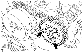
# Rotate the crankshaft pulley clockwise and temporarily plug the camshaft timing gear or sprocket with 2 screws fastening the camshaft timing gear indicated by the arrows in the figure. Then tighten the bolts to the moment of specification with 3 bolts.
Occasion:8.0 N * m {82 kgf * cm, 71 in .* lbf}
# Give the adhesive to 2 or 3 screw on the end of the stopper bolt cap screw holes servicing chain.
CAUTION:Keep the bolts and bolt holes are free from foreign matter and oil.
# Use a 10 mm hexagon key pretentious, plug the hole plug screw cap service chain.
Occasion:17 N * m {168 kgf * cm, 12 ft lbf .*}
# Replace the timing chain cover stars. 2.
# Give the packing seal as shown.Gaskets Sil:Toyota Genuine Seal Packing Black, Three Bond 1207B or equivalent
 # 2 Install the timing chain cover with 2 bolts.
Occasion:8.5 N * m {87 kgf * cm, 75 in .* lbf}
CAUTION:
* Clean any oil from the surface of contact.
* Replace the timing chain cover stars. 2 in 3 minutes after the use of packing seals.
* Do not start the engine at least 2 hours after installation.
# Install vibration damper 2 chain with 2 bolts.
 Occasion:8.5 N * m {87 kgf * cm, 75 in .* lbf}13.POST CYLINDER HEAD COVER SUB-ASSEMBLY
# Set the cylinder head cover gasket in groove head cover, and insert the gasket into the boss in the head cover.
CAUTION:Insert the gasket perfectly until contact with the ribs.# Give the packing seal as shown.Gaskets Sil:Toyota Genuine Seal Packing Black, Three Bond 1207B or equivalent
 INSTRUCTIONS:Seal packing must have a width of 5 mm and a height of 2 mm.
# For a pair of cylinder head cover with 11 bolts and 2 nuts.
 # Tighten bolts and nuts in several stages as shown in FIG.
Occasion:12 N * m {122 kgf * cm, 9 ft lbf .*} to bolt9.0 N * m {92 kgf * cm, 80 in lbf .*} for the nut
14.POST PIPE RADIATOR SUB-ASSEMBLY
15.POST CABLE MACHINE
16.POST NO 2 throttle body bracket
17.POST ASSEMBLY ignition coils
18.POST NO 2 ventilation hose
19.POST ventilation hose
20.POST AIR FILTER ASSEMBLY
 # Replace the air filter with 3 bolts
Occasion:7.5 N * m {76 kgf * cm, 66 in .* lbf}
# Connect the vacuum hose to the vacuum sensor.
# Connect the vacuum sensor.
# Replace the air temperature sensor.
# 2 Attach the hose to the VSV.
# Connect the VSV connector.
21.PUT HOSE AIR FILTERS NO 1
22.CONNECT CABLE TO NEGATIVE BATTERY TERMINAL
23.CHECK ENGINE OIL LEAK
All New Avanza & The All New Avanza Veloz
# Loosen the hose clamp and the air filter off the bolt, then remove the air cleaner hose No. 1.

# Disconnect the VSV connector.
# Remove the 2 hoses.
# Remove the air temperature sensor.
# Unplug the vacuum sensor.
# Remove the vacuum hose.
# Remove the 3 bolts, then remove the air filter sub-assembly.
3.OFF AIR FILTER ASSEMBLY
# Remove the four connectors.# Remove the four bolts, then the ignition coil assembly.

5.OFF VENTILATION HOSE
6.OFF VENTILATION HOSE NO 2
7.OFF THROTTLE BODY BRACKET NO 2
# Remove the 2 screws, then remove the throttle body bracket 2.
8.DETACH CABLE MACHINE
9.DETACH PIPE RADIATOR SUB-ASSEMBLY
Remove the 2 screws, then remove the radiator pipe sub-assembly.

# Remove the 11 bolts and 2 nuts in the order indicated in the figure, then the cylinder head.
11.CHECK SLIT VALVE
CAUTION:Check the valve gap in cold conditions.
# Set the 1 cylinder to TDC / compression.


# Check the valve gap shown in the picture.
* Use a feeler gauge, measure the gap between the valve lifter and camshaft.
Slit valve (Cold):Intake 0.145 to 0.235 mm (0.0057 to 0.0093-in.)Exhaust 0.275 to 0.365 mm (0.0108 to 0.0144-in.)

# Rotate the crankshaft clockwise one full turn and set cylinder No.. 4 to TDC / compression.
# Check the valve gap shown in the picture.
* Use a feeler gauge, measure the gap between the valve lifter and camshaft.
Slit valve (Cold):Intake 0.145 to 0.235 mm (0.0057 to 0.0093-in.)Exhaust 0.275 to 0.365 mm (0.0108 to 0.0144-in.)

12.SET THE SLIT VALVE
CAUTION:To prevent the valve does not collide with the piston when removing the camshaft, rotate the crankshaft in the direction of engine rotation approximately 90 ° from TDC / compression cylinder No.. 1.


# Check that the adjustment mark on the camshaft timing sprocket is facing up. If not, turn the crankshaft 1 round until the signs are facing upwards. (No. Cylinders. 1 at the position of TDC / compression).
# Give the paint mark on the timing chain is a straight plate with marks on the camshaft timing mark on camshaft sprocket and timing gear.
# Using a hexagonal lobes on the camshaft, loosen the screws that secure the camshaft timing sprocket.
CAUTION:The bolts can only be relaxed. Do not remove the bolts and sprockets.


# Insert the screwdriver into the hole closed service chain, then move the stopper plate on the tensioner downward and hold it so as not to lock.

# If the stopper does not release the lock plate easily, turn to the right and left to use hexagonal lobe on the camshaft.

# Remove the screwdriver from the hole closed chain services. Align the holes in the stopper plate and tensioner, then enter the lock hexagon diameter 2.5 mm (0.098-in.).
CAUTION:
*Hold the camshaft using the hexagonal lobe on the camshaft.
# Hold the diameter of 2.5 mm hexagon key (0098-in.) With adhesive tape so as not to be attracted to the outside.


# Use a micrometer, measure the thickness of the valve lifter that has been released.Calculate thick slit valve lifters so the valves are in the specification.
A. Choosing valve lifter.
B. Bold valve lifter is released.

Value specification (Cold):
Intake A = B + (C - 0.18 mm (0.0071-in.)).
Exhaust A = B + (C -0.31 mm (0.3099 mm.)).
# Select the new lifters with a thickness as close as possible to the value has been calculated.
INSTRUCTIONS:Lifter is available in 29 sizes with the addition of 0.020 mm (0.0008-in.), From 5.12 mm (0.2016-in.) Up to 5.68 mm (0.2236-in.).
Gap intake valves (Cold):Intake 0.15 to 0.23 mm (0.0059 to 0.2311 mm.)
EXAMPLE:Posted lifters 5.250 mm (5.2502 mm.), And the size of the gap is 0.400 mm (0.4013 mm.).Replace lifters 5.250 mm (5.2502 mm.) With a new size No.. 48 lifters.
New Lifter Thickness:No. Thickness No. Lifter. Thickness No. Lifter. Heavy Lifter
12 5,120 (0.2016) 32 5,320 (0.2094) 52 5,520 (0.2173)
14 5,140 (0.2024) 34 5,340 (0.2102) 54 5,540 (0.2181)
16 5,160 (0.2031) 36 5,360 (0.2110) 56 5,560 (0.2189)
18 5,180 (0.2039) 38 5,380 (0.2118) 58 5,580 (0.2197)
20 5,200 (0.2047) 40 5,400 (0.2126) 60 5,600 (0.2205)
22 5,220 (0.2055) 42 5,420 (0.2134) 62 5,620 (0.2213)
24 5,240 (0.2063) 44 5,440 (0.2142) 64 5,640 (0.2220)
26 5,260 (0.2071) 46 5,460 (0.2150) 66 5,660 (0.2228)
28 5,280 (0.2079) 48 5,480 (0.2157) 68 5,680 (0.2236)
30 5,300 (0.2087) 50 5,500 (0.2165) - -
Exhaust valve gap (Cold):Exhaust 0.28 to 0.36 mm (0.0110 to 0.3607 mm.)
EXAMPLE:Posted lifters 5.340 mm (0.2102-in.), And the size of the gap is 0.440 mm (0.0173-in.).Replace lifters 5.340 mm (0.2102-in.) With a new size No.. 46 lifters.
New Lifter Thickness:
No. Thickness No. Lifter. Thickness No. Lifter. Heavy Lifter12 5,120 (00002016) 32 5,320 (0.2094) 52 5,520 (0.2173)
14 5,140 (0.2024) 34 5,340 (0.2102) 54 5,540 (0.2181)
16 5,160 (0.2031) 36 5,360 (0.2110) 56 5,560 (0.2189)
18 5,180 (0.2039) 38 5,380 (0.2118) 58 5,580 (0.2197)
20 5,200 (0.2047) 40 5,400 (0.2126) 60 5,600 (0.2205)
22 5,220 (0.2055) 42 5,420 (0.2134) 62 5,620 (0.2213)
24 5,240 (0.2063) 44 5,440 (0.2142) 64 5,640 (0.2220)
26 5,260 (0.2071) 46 5,460 (0.2150) 66 5,660 (0.2228)
28 5,280 (0.2079) 48 5,480 (0.2157) 68 5,680 (0.2236)
30 5,300 (0.2087) 50 5,500 (0.2165 - -
# Replace the valve lifter is selected.
# Give the engine oil on the cam, cylinder head journaling, and above the valve lifters.

# Check the front sign and the number and check that the sequence of stages as shown in the picture. Tighten the bolts in several stages as shown in FIG.
# For a pair of camshaft timing sprocket with the bolt.
# For the 2 pairs of camshaft sprocket with the bolt.
# Attach the chain so that the adjustment marks on the camshaft sprocket timing marks and paint, are made prior to demolition chains, have been straight.
INSTRUCTIONS:First, attach the chain to one of the camshaft. Rotate the camshaft to the right and to left using the hexagonal lobes on the camshaft timing so that the signs and signs painted on the sprocket on the chain to be straight.
Hexagon key Prison
# diameter 2.5 mm (0.098-in.) Of the tensioner.
INSTRUCTIONS:Using a hexagonal lobes on the camshaft, rotate the camshaft slightly to the left, then release the key Hexagon 2.5 mm in diameter (0098-in.) With a loose chain on the side of the tensioner.
# Using a hexagonal lobes on the camshaft, tighten the bolts used to mount the sprocket to the camshaft timing specifications moment.
Occasion:47 N * m {479 kgf * cm, 35 ft lbf .*}
# Give the adhesive on 2 or 3 screw on the end of the stopper bolt cap screw holes servicing chain.
CAUTION:Clean the oil contained in the bolts and bolt holes.
# Rotate the crankshaft pulley clockwise and temporarily plug the camshaft timing gear or sprocket with 2 screws fastening the camshaft timing gear indicated by the arrows in the figure. Then tighten the bolts to the moment of specification with 3 bolts.
Occasion:8.0 N * m {82 kgf * cm, 71 in .* lbf}
# Give the adhesive to 2 or 3 screw on the end of the stopper bolt cap screw holes servicing chain.
CAUTION:Keep the bolts and bolt holes are free from foreign matter and oil.
# Use a 10 mm hexagon key pretentious, plug the hole plug screw cap service chain.
Occasion:17 N * m {168 kgf * cm, 12 ft lbf .*}
# Replace the timing chain cover stars. 2.
# Give the packing seal as shown.Gaskets Sil:Toyota Genuine Seal Packing Black, Three Bond 1207B or equivalent

Occasion:8.5 N * m {87 kgf * cm, 75 in .* lbf}
CAUTION:
* Clean any oil from the surface of contact.
* Replace the timing chain cover stars. 2 in 3 minutes after the use of packing seals.
* Do not start the engine at least 2 hours after installation.
# Install vibration damper 2 chain with 2 bolts.

# Set the cylinder head cover gasket in groove head cover, and insert the gasket into the boss in the head cover.
CAUTION:Insert the gasket perfectly until contact with the ribs.# Give the packing seal as shown.Gaskets Sil:Toyota Genuine Seal Packing Black, Three Bond 1207B or equivalent

# For a pair of cylinder head cover with 11 bolts and 2 nuts.

Occasion:12 N * m {122 kgf * cm, 9 ft lbf .*} to bolt9.0 N * m {92 kgf * cm, 80 in lbf .*} for the nut
14.POST PIPE RADIATOR SUB-ASSEMBLY
15.POST CABLE MACHINE
16.POST NO 2 throttle body bracket
17.POST ASSEMBLY ignition coils
18.POST NO 2 ventilation hose
19.POST ventilation hose
20.POST AIR FILTER ASSEMBLY

Occasion:7.5 N * m {76 kgf * cm, 66 in .* lbf}
# Connect the vacuum hose to the vacuum sensor.
# Connect the vacuum sensor.
# Replace the air temperature sensor.
# 2 Attach the hose to the VSV.
# Connect the VSV connector.
21.PUT HOSE AIR FILTERS NO 1
22.CONNECT CABLE TO NEGATIVE BATTERY TERMINAL
23.CHECK ENGINE OIL LEAK
All New Avanza & The All New Avanza Veloz


